http://en.wikipedia.org/wiki/High-pass_filter
High-pass filter
[edit]First-order continuous-time implementation
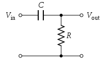
Figure 1: A passive, analog, first-order high-pass filter, realized by an
RC circuit
The simple first-order electronic high-pass filter shown in Figure 1 is implemented by placing an input voltage across the series combination of a
capacitor and a
resistor and using the voltage across the resistor as an output. The product of the resistance and capacitance (
R×
C) is the
time constant (τ); it is inversely proportional to the cutoff frequency
fc, that is,


Figure 2: An active high-pass filter
Figure 2 shows an active electronic implementation of a first-order high-pass filter using an
operational amplifier. In this case, the filter has a
passband gain of -
R2/
R1 and has a corner frequency of
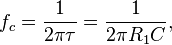
Because this filter is
active, it may have
non-unity passband gain. That is, high-frequency signals are inverted and amplified by
R2/
R1.
[edit]Discrete-time realization
For another method of conversion from continuous- to discrete-time, see
Bilinear transform.
Discrete-time high-pass filters can also be designed. Discrete-time filter design is beyond the scope of this article; however, a simple example comes from the conversion of the continuous-time high-pass filter above to a discrete-time realization. That is, the continuous-time behavior can be
discretized.

where

is the charge stored in the capacitor at time

. Substituting Equation (Q) into Equation (I) and then Equation (I) into Equation (V) gives:

This equation can be discretized. For simplicity, assume that samples of the input and output are taken at evenly-spaced points in time separated by

time. Let the samples of

be represented by the sequence

, and let

be represented by the sequence

which correspond to the same points in time. Making these substitutions:


That is, this discrete-time implementation of a simple continuous-time RC high-pass filter is

By definition,

. The expression for parameter

yields the equivalent
time constant 
in terms of the sampling period
and
:

If

, then the
time constant equal to the sampling period. If

, then
is significantly smaller than the sampling interval, and

.
[edit]Algorithmic implementation
The filter recurrence relation provides a way to determine the output samples in terms of the input samples and the preceding output. The following
pseudocode algorithm will simulate the effect of a high-pass filter on a series of digital samples:
 // Return RC high-pass filter output samples, given input samples,
 // time interval dt, and time constant RC
 function highpass(real[0..n] x, real dt, real RC)
   var real[0..n] y
   var real α := RC / (RC + dt)
   y[0] := x[0]
   for i from 1 to n
     y[i] := α * y[i-1] + α * (x[i] - x[i-1])
   return y
The loop which calculates each of the

outputs can be
refactored into the equivalent:
   for i from 1 to n
     y[i] := α * (y[i-1] + x[i] - x[i-1])
However, the earlier form shows how the parameter α changes the impact of the prior output y[i-1] and current changein input (x[i] - x[i-1]). In particular,
- A large α implies that the output will decay very slowly but will also be strongly influenced by even small changes in input. By the relationship between parameter α and time constant above, a large α corresponds to a large and therefore a low corner frequency of the filter. Hence, this case corresponds to a high-pass filter with a very narrow stop band. Because it is excited by small changes and tends to hold its prior output values for a long time, it can pass relatively low frequencies. However, a constant input (i.e., an input with (x[i] - x[i-1])=0) will always decay to zero, as would be expected with a high-pass filter with a large .
- A small α implies that the output will decay quickly and will require large changes in the input (i.e., (x[i] - x[i-1]) is large) to cause the output to change much. By the relationship between parameter α and time constant above, a small α corresponds to a small and therefore a high corner frequency of the filter. Hence, this case corresponds to a high-pass filter with a very wide stop band. Because it requires large (i.e., fast) changes and tends to quickly forget its prior output values, it can only pass relatively high frequencies, as would be expected with a high-pass filter with a small .
[edit]Applications
High-pass filters have many applications. They are used as part of an
audio crossover to direct high frequencies to a
tweeter while attenuating bass signals which could interfere with, or damage, the speaker. When such a filter is built into a
loudspeaker cabinet it is normally a
passive filter that also includes a
low-pass filter for the
woofer and so often employs both a capacitor and
inductor (although very simple high-pass filters for tweeters can consist of a series capacitor and nothing else). As an example, the
formula above, applied to a tweeter with R=10 Ohm, will determine the capacitor value for a cut-off frequency of 5 KHz.

, or approx 3.2 μF.
An alternative, which provides good quality sound without inductors (which are prone to parasitic coupling, are expensive, and may have significant internal resistance) is to employ
bi-amplification with
active RC filters or active digital filters with separate power amplifiers for each
loudspeaker. Such low-current and low-voltage
line level crossovers are called
active crossovers.
[1]
Rumble filters are high-pass filters applied to the removal of unwanted sounds near to the lower end of the
audible range or below. For example, noises (e.g., footsteps, or motor noises from
record players and
tape decks) may be removed because they are undesired or may overload the
RIAA equalization circuit of the
preamp.
[1]
High-pass filters are also used for
AC coupling at the inputs of many
audio power amplifiers, for preventing the amplification of DC currents which may harm the amplifier, rob the amplifier of headroom, and generate waste heat at the
loudspeakersvoice coil. One amplifier, the
professional audio model DC300 made by
Crown International beginning in the 1960s, did not have high-pass filtering at all, and could be used to amplify the DC signal of a common 9-volt battery at the input to supply 18 volts DC in an emergency for
mixing console power.
[2] However, that model's basic design has been superseded by newer designs such as the Crown Macro-Tech series developed in the late 1980s which included 10 Hz high-pass filtering on the inputs and switchable 35 Hz high-pass filtering on the outputs.
[3] Another example is the
QSC Audio PLX amplifier series which includes an internal 5 Hz high-pass filter which is applied to the inputs whenever the optional 50 and 30 Hz high-pass filters are turned off.
[4]

A 75 Hz "low cut" filter from an input channel of a
Mackie 1402
mixing console as measured by
Smaart software. This high-pass filter has a slope of 18 dB per octave.
Mixing consoles often include high-pass filtering at each
channel strip. Some models have fixed-slope, fixed-frequency high-pass filters at 80 or 100 Hz that can be engaged; other models have 'sweepable HPF'—a high-pass filter of fixed slope that can be set within a specified frequency range, such as from 20 to 400 Hz on the
Midas Heritage 3000, or 20 to 20,000 Hz on the
Yamaha M7CLdigital mixing console. Veteran systems engineer and live sound mixer Bruce Main recommends that high-pass filters be engaged for most mixer input sources, except for those such as
kick drum,
bass guitar and piano, sources which will have useful low frequency sounds. Main writes that
DI unit inputs (as opposed to
microphone inputs) do not need high-pass filtering as they are not subject to modulation by low-frequency
stage wash—low frequency sounds coming from the
subwoofers or the
public address system and wrapping around to the stage. Main indicates that high-pass filters are commonly used for directional microphones which have a
proximity effect—a low-frequency boost for very close sources. This low frequency boost commonly causes problems up to 200 or 300 Hz, but Main notes that he has seen microphones that benefit from a 500 Hz HPF setting on the console.
[5]

Example of high-pass filter applied to the right half of a photograph. Left side is unmodified, Right side is with a high-pass filter applied (in this case, with a radius of 4.9)
A high-pass filter, if the imaging software does not have one, can be done by duplicating the layer, putting a gaussian blur, inverting, and then blending with the original layer using an opacity (say 50%) with the original layer.
[7]
The
unsharp masking, or sharpening, operation used in image editing software is a high-boost filter, a generalization of high-pass.


 ;
;


