Friday 4 January 2013

The Series Circuit

http://www.regentsprep.org/regents/physics/phys03/bsercir/default.htm


The Series Circuit


series circuit has more than one resistor (anything that uses electricity to do work) and gets its name from only having one path for the charges to move along. Charges must move in "series" first going to one resistor then the next. If one of the items in the circuit is broken then no charge will move through the circuit because there is only one path. There is no alternative route. Old style electric holiday lights were often wired in series. If one bulb burned out, the whole string of lights went off.
Below is an animation of a series circuit where electrical energy is shown as gravitational potential energy (GPE). The greater the change in height, the more energy is used or the more work is done.


In this animation you should notice the following things:
  • The battery or source is represented by an escalator which raises charges to a higher level of energy.
  • As the charges move through the resistors (represented by the paddle wheels) they do work on the resistor and as a result, they lose electrical energy.
  • The charges do more work (give up more electrical energy) as they pass through the larger resistor.
  • By the time each charge makes it back to the battery, it has lost all the energy given to it by the battery.
  • The total of the potential drops ( - potential difference) across the resistors is the same as the potential rise ( +potential difference) across the battery. This demonstrates that a charge can only do as much work as was done on it by the battery.
  • The charges are positive so this is a representation of Conventional Current (the apparent flow of positive charges)
  • The charges are only flowing in one direction so this would be considered direct current ( D.C. ).
The following rules apply to a series circuit:
  1. The sum of the potential drops equals the potential rise of the source.
  2. The current is the same everywhere in the series circuit.
  3. The total resistance of the circuit (also called effective resistance) is equal to the sum of the individual resistances.

Ohm's Law may be used in a series circuit as long as you remember that you can use the formula with either partial values or with total values but you can not mix parts and totals.


The Parallel Circuit


http://www.regentsprep.org/regents/physics/phys03/bparcir/default.htm

The Parallel Circuit


parallel circuit has more than one resistor (anything that uses electricity to do work) and gets its name from having multiple (parallel) paths to move along . Charges can move through any of several paths. If one of the items in the circuit is broken then no charge will move through that path, but other paths will continue to have charges flow through them. Parallel circuits are found in most household electrical wiring. This is done so that lights don't stop working just because you turned your TV off.
Below is an animation of a parallel circuit where electrical energy is shown as gravitational potential energy (GPE). The greater the change in height, the more energy is used or the more work is done.


In this animation you should notice the following things:
  • More current flows through the smaller resistance. (More charges take the easiest path.)
  • The battery or source is represented by an escalator which raises charges to a higher level of energy.
  • As the charges move through the resistors (represented by the paddle wheels) they do work on the resistor and as a result, they lose electrical energy.
  • By the time each charge makes it back to the battery, it has lost all the electrical energy given to it by the battery.
  • The total of the potential drops ( - potential difference) of each "branch" or path is the same as the potential rise ( + potential difference) across the battery. This demonstrates that a charge can only do as much work as was done on it by the battery.
  • The charges are positive so this is a representation of conventional current (the apparent flow of positive charges)
  • The charges are only flowing in one direction so this would be considered direct current ( D.C. ).
The following rules apply to a parallel circuit:
  1. The potential drops of each branch equals the potential rise of the source.
  2. The total current is equal to the sum of the currents in the branches.
  3. The inverse of the total resistance of the circuit (also called effective resistance) is equal to the sum of the inverses of the individual resistances.

    One important thing to notice from this last equation is that the more branches you add to a parallel circuit (the more things you plug in) the lower the total resistance becomes. Remember that as the total resistance decreases, the total current increases. So, the more things you plug in, the more current has to flow through the wiring in the wall. That's why plugging too many things in to one electrical outlet can create a real fire hazard.


Ohm's Law may be used in a parallel circuit as long as you remember that you can use the formula with eitherpartial values or with total values but you can not mix parts and totals.


Types of electronic circuits


http://electroniccircuitsforbeginners.blogspot.in/2009/04/types-of-circuits.html
Types of circuits

From the smallest circuit to the largest electronics project, every circuit that performs a useful function has one or more of the same building blocks. I’m not talking about electronic components; I’m talking about sub-circuits that have a defined function.

These circuits are divided in digital and analog. In these pages you’ll learn how to design every type of circuit listed, with emphasis on a functionality level, instead of a component level, in order to be able to create any kind of amplifier as required by the project. Here’s the list of them:


Analog


  • Amplifiers
  • Filters
  • Power sources
  • Oscillators
  • Rectifiers
  • Timers
  • Modulators
  • Demodulators


Digital
  • Logic gates
  • Counters
  • Encoders
  • Decoders
  • Flip-Flops
  • Multiplexers
  • Demultiplexers
  • Analog to Digital Converter (ADC)
  • Digital to Analog Converter (DAC)
  • Microcontrollers
  • Microprocessors
All of these sub-circuits have a defined function within a complete project, and some of them are even a project on their own. These categories are somewhat broad; every one of them has many different designs and implementations depending on the particular characteristics of the project, for example amplifiers.

There are transistor and OpAmp amplifiers. In transistor amplifiers there are common source, common base, common collector, there are Darlington amplifiers. Transistor amplifiers are further divided by the kind of transistor used: BJT, N-channel JFET, P-channel JFET, MosFET, Nmos, Pmos, Cmos; Each with its own set of configurations.

On OpAmp there are negative feedback, positive feedback, voltage follower and others.
As you can see there are a million different combinations of amplifier topologies as they are called, way too many to be familiar with all of them.

Galvanometer


http://hyperphysics.phy-astr.gsu.edu/hbase/magnetic/galvan.html


Galvanometer


Galvanometer is the historical name given to a moving coil electric current detector. When a current is passed through a coil in a magnetic field, the coil experiences a torqueproportional to the current. If the coil's movement is opposed by a coil spring, then the amount of deflection of a needle attached to the coil may be proportional to the current passing through the coil. Such "meter movements" were at the heart of the moving coil meters such as voltmeters and ammetersuntil they were largely replaced with solid state meters.
The accuracy of moving coil meters is dependent upon having a uniform and constant magnetic field. The illustration shows one configuration of permanent magnet which was widely used in such meters.


Galvanometer
     
        The torque on a current loop in a uniform magnetic field is used to measure electrical magnetic field is used to measure electrical currents.  This current measuring device is called a moving coil galvanometer.  
                    
        The galvanometer consists of a coil of wire often rectangular, carrying the current to be measured.  There are generally many turns in the coil to increase its sensitivity.  The coil is placed in a magnetic field such that the lines of B remain nearly parallel to the plane of wire as it turns.  This is achieved by having a soft iron cylinder placed at the center of the coil.  Magnetic field lines tend to pass through the iron cylinder, producing the field configuration. The moving coil is hung from a spring which winds up as the coil rotates; this winding up produces a restoring torque proportional to the winding up (or twisting) of the spring, i.e. to the angular deflection of the coil.  The coil comes to equilibrium when this restoring torque k balances the torque due to the magnetic field balances the torque due to the magnetic field.  Since by design field lines are radial, 
we have  sin q ~ 1, so that for equilibrium
                                                k ø = INBA

                                                                        NBA
                                                               ø = ------ I
                                                                          k
        Thus the deflection  ø of the galvanometer is proportional to the electric current I passing through it
.

Ammeter

http://people.ee.duke.edu/~cec/final/node22.html

Ammeter

An ideal ammeter has zero resistance so that the the circuit in which it has been placed is not disturbed. An ideal ammeter is a short circuit. However, as with the voltmeter, no ammeter can ever be ideal, and therefore all ammeters have some ( hopefully) small internal resistance. To determine the resistance of the ammeter, we will use the circuit in Figure gif. According to Ohm's Law, the current in this circuit will be  where . So the current can be found using the equation:
 
By using the known quantities  and R, we can solve for the unknown quantity .
In the procedure that follows it is extremely important that you take precise and accurate measurements. Record each measurement as precisely as the instrument will allow.
  1. Select a 100  resistor. Measure and record its actual value.
  2. Assemble the circuit in Figure gif. Set the multimeter to the ammeter mode for dc current measurement. Recall this means two things: Place the test leads in the correct banana jacks and press the proper sequence of softkeys.
  3. Use the oscilloscope to measure the voltage across the DC power supply.
  4. Measure the value of the current using the ammeter.
  5. Determine the value of  from Equation gif.

Voltmeter


http://people.ee.duke.edu/~cec/final/node21.html


Voltmeter

An ideal voltmeter has infinite resistance: It is an open circuit. Although it is impossible to make a physical voltmeter with infinite resistance, a well designed voltmeter exhibits a very large internal input resistance. In some experiments, it is important to take into account the finite, non-ideal, internal resistance. To determine the internal resistance of the voltmeter, set up the circuit shown in figure gif. The voltmeter reads the voltage across itself, which includes its internal resistance. Since the circuit has only a single branch, the current flowing through the resistor also flows through the voltmeter. The current is given by the equation:

From Ohm's Law, if we know the current (I) and the voltage () we can compute .


Figure: Circuit for measuring the resistance of the voltmeter.


  1. Select a 1  resistor.
  2. Measure its value using the multimeter.
  3. Set the power supply to provide 10 V (Remember, always measure the voltage provided by the power supply with either the voltmeter or the scope. Do not rely on the digital display on the front panel of the power supply.)
  4. Assemble the circuit in Figure gif.
  5. Record the voltage measured by the voltmeter
  6. Compute the internal resistance of the voltmeter using Equation gif.

Battery


http://en.wikipedia.org/wiki/Battery_(electricity)

Battery


A battery is a device that converts chemical energy directly to electrical energy.[22] It consists of a number of voltaic cells; each voltaic cell consists of two half-cells connected in series by a conductive electrolyte containing anions and cations. One half-cell includes electrolyte and the electrode to which anions (negatively charged ions) migrate, i.e., theanode or negative electrode; the other half-cell includes electrolyte and the electrode to which cations (positively charged ions) migrate, i.e., thecathode or positive electrode. In the redox reaction that powers the battery, cations are reduced (electrons are added) at the cathode, while anions are oxidized (electrons are removed) at the anode.[23] The electrodes do not touch each other but are electrically connected by theelectrolyte. Some cells use two half-cells with different electrolytes. A separator between half-cells allows ions to flow, but prevents mixing of the electrolytes.
Each half-cell has an electromotive force (or emf), determined by its ability to drive electric current from the interior to the exterior of the cell. The net emf of the cell is the difference between the emfs of its half-cells, as first recognized by Volta.[12] Therefore, if the electrodes have emfs \mathcal{E}_1 and \mathcal{E}_2, then the net emf is \mathcal{E}_{2}-\mathcal{E}_{1}; in other words, the net emf is the difference between the reduction potentials of the half-reactions.[24]
The electrical driving force or \displaystyle{\Delta V_{bat}} across the terminals of a cell is known as the terminal voltage (difference) and is measured in volts.[25] The terminal voltage of a cell that is neither charging nor discharging is called the open-circuit voltage and equals the emf of the cell. Because of internal resistance,[26] the terminal voltage of a cell that is discharging is smaller in magnitude than the open-circuit voltage and the terminal voltage of a cell that is charging exceeds the open-circuit voltage.[27] An ideal cell has negligible internal resistance, so it would maintain a constant terminal voltage of \mathcal{E} until exhausted, then dropping to zero. If such a cell maintained 1.5 volts and stored a charge of one coulomb then on complete discharge it would perform 1.5 joule of work.[25] In actual cells, the internal resistance increases under discharge,[26] and the open circuit voltage also decreases under discharge. If the voltage and resistance are plotted against time, the resulting graphs typically are a curve; the shape of the curve varies according to the chemistry and internal arrangement employed.[28]
As stated above, the voltage developed across a cell's terminals depends on the energy release of the chemical reactions of its electrodes and electrolyte. Alkaline and zinc–carbon cells have different chemistries but approximately the same emf of 1.5 volts; likewise NiCd and NiMH cells have different chemistries, but approximately the same emf of 1.2 volts.[29] On the other hand the high electrochemical potential changes in the reactions of lithium compounds give lithium cells emfs of 3 volts or more.[30]

Categories and types of batteries

From top to bottom: a large 4.5-volt (3R12) battery, a D Cell, a C cell, an AA cell, an AAA cell, anAAAA cell, an A23 battery, a 9-volt PP3 battery, and a pair ofbutton cells (CR2032 and LR44).
Batteries are classified into two broad categories, each type with advantages and disadvantages.[31]
  • Primary batteries irreversibly (within limits of practicality) transform chemical energy to electrical energy. When the initial supply of reactants is exhausted, energy cannot be readily restored to the battery by electrical means.[32]
  • Secondary batteries can be recharged; that is, they can have their chemical reactions reversed by supplying electrical energy to the cell, restoring their original composition.[33]
Some types of primary batteries used, for example, for telegraph circuits, were restored to operation by replacing the components of the battery consumed by the chemical reaction.[34] Secondary batteries are not indefinitely rechargeable due to dissipation of the active materials, loss of electrolyte and internal corrosion.

Primary batteries

Primary batteries can produce current immediately on assembly. Disposable batteries are intended to be used once and discarded. These are most commonly used in portable devices that have low current drain, are used only intermittently, or are used well away from an alternative power source, such as in alarm and communication circuits where other electric power is only intermittently available. Disposable primary cells cannot be reliably recharged, since the chemical reactions are not easily reversible and active materials may not return to their original forms. Battery manufacturers recommend against attempting to recharge primary cells.[35]
Common types of disposable batteries include zinc–carbon batteries and alkaline batteries. In general, these have higher energy densities than rechargeable batteries,[36] but disposable batteries do not fare well under high-drain applications with loads under 75 ohms (75 Ω).[31]

Secondary batteries

Secondary batteries must be charged before use; they are usually assembled with active materials in the discharged state. Rechargeable batteries orsecondary cells can be recharged by applying electric current, which reverses thechemical reactions that occur during its use. Devices to supply the appropriate current are called chargers or rechargers.
The oldest form of rechargeable battery is the lead–acid battery.[37] This battery is notable in that it contains a liquid in an unsealed container, requiring that the battery be kept upright and the area be well ventilated to ensure safe dispersal of the hydrogen gas produced by these batteries during overcharging. The lead–acid battery is also very heavy for the amount of electrical energy it can supply. Despite this, its low manufacturing cost and its high surge current levels make its use common where a large capacity (over approximately 10 Ah) is required or where the weight and ease of handling are not concerns.
A common form of the lead–acid battery is the modern car battery, which can, in general, deliver a peak current of 450 amperes.[38] An improved type of liquid electrolyte battery is the sealed valve regulated lead–acid battery (VRLA battery), popular in the automotive industry as a replacement for the lead–acid wet cell. The VRLA battery uses an immobilized sulfuric acid electrolyte, reducing the chance of leakage and extending shelf life.[39] VRLA batteries have the electrolyte immobilized, usually by one of two means:
  • Gel batteries (or "gel cell") contain a semi-solid electrolyte to prevent spillage.
  • Absorbed Glass Mat (AGM) batteries absorb the electrolyte in a special fiberglass matting.
Other portable rechargeable batteries include several "dry cell" types, which are sealed units and are, therefore, useful in appliances such as mobile phones and laptop computers. Cells of this type (in order of increasing power density and cost) include nickel–cadmium (NiCd), nickel–zinc (NiZn), nickel metal hydride (NiMH), and lithium-ion(Li-ion) cells.[40] By far, Li-ion has the highest share of the dry cell rechargeable market.[3] Meanwhile, NiMH has replaced NiCd in most applications due to its higher capacity, but NiCd remains in use in power toolstwo-way radios, and medical equipment.[3] NiZn is a new technology that is not yet well established commercially.
Recent developments include batteries with embedded electronics such as USBCELL, which allows charging an AA cell through a USB connector,[41] and smart battery packs with state-of-charge monitors and battery protection circuits to prevent damage on over-discharge. low self-discharge (LSD) allows secondary cells to be precharged prior to shipping.

Battery cell types

There are many general types of electrochemical cells, according to chemical processes applied and design chosen. The variation includes galvanic cellselectrolytic cellsfuel cellsflow cells and voltaic piles.[42]

Wet cell

wet cell battery has a liquid electrolyte. Other names are flooded cell, since the liquid covers all internal parts, orvented cell, since gases produced during operation can escape to the air. Wet cells were a precursor to dry cells and are commonly used as a learning tool for electrochemistry. It is often built with common laboratory supplies, such as beakers, for demonstrations of how electrochemical cells work. A particular type of wet cell known as aconcentration cell is important in understanding corrosion. Wet cells may be primary cells (non-rechargeable) orsecondary cells (rechargeable). Originally, all practical primary batteries such as the Daniell cell were built as open-topped glass jar wet cells. Other primary wet cells are the Leclanche cellGrove cellBunsen cellChromic acid cellClark cell, and Weston cell. The Leclanche cell chemistry was adapted to the first dry cells. Wet cells are still used in automobile batteries and in industry for standby power for switchgear, telecommunication or largeuninterruptible power supplies, but in many places batteries with gel cells have been used instead. These applications commonly use lead–acid or nickel–cadmium cells.

Dry cell

Line art drawing of a dry cell:
1. brass cap, 2. plastic seal, 3. expansion space, 4. porous cardboard, 5. zinc can, 6. carbon rod, 7. chemical mixture.
dry cell has the electrolyte immobilized as a paste, with only enough moisture in it to allow current to flow. Unlike a wet cell, a dry cell can operate in any orientation without spilling as it contains no free liquid, making it suitable for portable equipment. By comparison, the first wet cells were typically fragile glass containers with lead rods hanging from the open top, and needed careful handling to avoid spillage. Lead–acid batteries did not achieve the safety and portability of the dry cell until the development of the gel battery.
A common dry cell battery is the zinc–carbon battery, using a cell sometimes called the dry Leclanché cell, with a nominal voltage of 1.5 volts, the same as thealkaline battery (since both use the same zincmanganese dioxide combination).
A standard dry cell comprises a zinc anode (negative pole), usually in the form of a cylindrical pot, with a carbon cathode (positive pole) in the form of a central rod. The electrolyte is ammonium chloride in the form of a paste next to the zinc anode. The remaining space between the electrolyte and carbon cathode is taken up by a second paste consisting of ammonium chloride and manganese dioxide, the latter acting as a depolariser. In some more modern types of so-called 'high-power' batteries (with much lower capacity than standard alkaline batteries), the ammonium chloride is replaced by zinc chloride.

Molten salt

Molten salt batteries are primary or secondary batteries that use a molten salt as electrolyte. Their energy densityand power density give them potential for use in electric vehicles, but they operate at high temperatures and must be well insulated to retain heat.

Reserve

reserve battery is stored in unassembled form and is activated, ready-charged, when its internal parts are assembled, e.g. by adding electrolyte; it can be stored unactivated for a long period of time. For example, a battery for an electronic fuze might be activated by the impact of firing a gun, breaking a capsule of electrolyte to activate the battery and power the fuze's circuits. Reserve batteries are usually designed for a short service life (seconds or minutes) after long storage (years). A water-activated battery for oceanographic instruments or military applications becomes activated on immersion in water.

Battery cell performance

A battery's characteristics may vary over load cycle, over charge cycle, and over lifetime due to many factors including internal chemistry, current drain, and temperature.

Potentiometer(Rheostat) - Wiki(Description)


Potentiometer(Rheostat)

potentiometer (pron.: /pɵˌtɛnʃiˈɒmɨtər/), informally a pot, is a three-terminal resistor with a sliding contact that forms an adjustablevoltage divider.[1] If only two terminals are used, one end and the wiper, it acts as a variable resistor or rheostat.
potentiometer measuring instrument is essentially a voltage divider used for measuring electric potential (voltage); the component is an implementation of the same principle, hence its name.
Potentiometers are commonly used to control electrical devices such as volume controls on audio equipment. Potentiometers operated by a mechanism can be used as position transducers, for example, in ajoystick. Potentiometers are rarely used to directly control significant power (more than a watt), since the power dissipated in the potentiometer would be comparable to the power in the controlled load.

Potentiometer.jpg
PCB mount trimmer potentiometers, or "trimpots", intended for infrequent adjustment.

Contents

  [hide

[edit]Potentiometer construction

Potentiometers comprise a resistive element, a sliding contact (wiper) that moves along the element, making good electrical contact with one part of it, electrical terminals at each end of the element, a mechanism that moves the wiper from one end to the other, and a housing containing the element and wiper.
Many inexpensive potentiometers are constructed with a resistive element formed into an arc of a circle usually a little less than a full turn, and a wiper rotating around the arc and contacting it. The resistive element, with a terminal at each end, is flat or angled. The wiper is connected to a third terminal, usually between the other two. On panel potentiometers, the wiper is usually the center terminal of three. For single-turn potentiometers, this wiper typically travels just under one revolution around the contact. The only point of ingress for contamination is the narrow space between the shaft and the housing it rotates in.
Another type is the linear slider potentiometer, which has a wiper which slides along a linear element instead of rotating. Contamination can potentially enter anywhere along the slot the slider moves in, making effective sealing more difficult and compromising long-term reliability. An advantage of the slider potentiometer is that the slider position gives a visual indication of its setting. While the setting of a rotary potentiometer can be seen by the position of a marking on the knob, an array of sliders can give a visual impression of, for example, the effect of a multi-channel equaliser.
The resistive element of inexpensive potentiometers is often made of graphite. Other materials used include resistance wire, carbon particles in plastic, and a ceramic/metal mixture called cermet. Conductive track potentiometers use conductive polymer resistor pastes that contain hard-wearing resins and polymers, solvents, and lubricant, in addition to the carbon that provides the conductive properties. Others are enclosed within the equipment and are intended to be adjusted to calibrate equipment during manufacture or repair, and not otherwise touched. They are usually physically much smaller than user-accessible potentiometers, and may need to be operated by a screwdriver rather than having a knob. They are usually called "preset potentiometers". Some presets are accessible by a small screwdriver poked through a hole in the case to allow servicing without dismantling.
Multiturn potentiometers are also operated by rotating a shaft, but by several turns rather than less than a full turn. Some multiturn potentiometers have a linear resistive element with a slider which moves along it moved by a worm gear; others have a helical resistive element and a wiper that turns through 10, 20, or more complete revolutions, moving along the helix as it rotates. Multiturn potentiometers, both user-accessible and preset, allow finer adjustments; rotation through the same angle changes the setting by typically a tenth as much as for a simple rotary potentiometer.
string potentiometer is a multi-turn potentiometer operated by an attached reel of wire turning against a spring, enabling it to convert linear position to a variable resistance.
User-accessible rotary potentiometers can be fitted with a switch which operates usually at the anti-clockwise extreme of rotation. Before digital electronics became the norm such a component was used to allow radio and television receivers and other equipment to be switched on at minimum volume with an audible click, then the volume increased, by turning a knob. Multiple resistance elements can be ganged together and controlled by the same shaft, for example, in stereo audio amplifiers for volume control.

[edit]Resistance–position relationship: "taper"

The relationship between slider position and resistance, known as the "taper" or "law", is controlled by the manufacturer. In principle any relationship is possible, but for most purposes linear or logarithmic (aka "audio taper") potentiometers are sufficient.
A letter code may be used to identify which taper is used, but the letter code definitions are not standardized. Newer potentiometers will usually be marked with an 'A' for logarithmic taper or a 'B' for linear taper. Older potentiometers may be marked with an 'A' for linear taper, a 'C' for logarithmic taper or a 'F' for anti-logarithmic taper. When a percentage is referenced, with a non-linear taper, it relates to the resistance value at the mid-point of the shaft rotation. A 10% log taper would therefore measure 10% of the total resistance at the mid point of the rotation; i.e. 10% log taper on a 10K ohm potentiometer would yield 1K at the mid point. The higher the percentage the steeper the log curve[2]

[edit]Linear taper potentiometer

linear taper potentiometer (linear describes the electrical characteristic of the device, not the geometry of the resistive element) has a resistive element of constant cross-section, resulting in a device where the resistance between the contact (wiper) and one end terminal is proportional to the distance between them. Linear taper potentiometers are used when the division ratio of the potentiometer must be proportional to the angle of shaft rotation (or slider position), for example, controls used for adjusting the centering of an analog cathode-rayoscilloscope.

[edit]Logarithmic potentiometer

logarithmic taper potentiometer has a resistive element that either 'tapers' in from one end to the other, or is made from a material whose resistivity varies from one end to the other. This results in a device where output voltage is a logarithmic function of the slider position.
Most (cheaper) "log" potentiometers are not accurately logarithmic, but use two regions of different resistance (but constant resistivity) to approximate a logarithmic law. The two resistive tracks overlap at approximately 50% of the potentiometer rotation, this gives a stepwise logarithmic taper.[3] A logarithmic potentiometer can also be simulated (not very accurately) with a linear one and an external resistor. True logarithmic potentiometers are significantly more expensive.
Logarithmic taper potentiometers are often used in connection with audio amplifiers as human perception of audio volume is logarithmic.
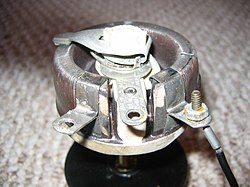
A high power wirewound potentiometer. Any potentiometer may be connected as a rheostat.

[edit]Rheostat

The most common way to vary the resistance in a circuit is to use a rheostat,[4] a two-terminal variable resistor. For low-power applications (less than about 1 watt) a three-terminal potentiometer is often used, with one terminal unconnected or connected to the wiper.
Where the rheostat must be rated for higher power (more than about 1 watt), they may be built with a resistance wire wound around a semicircular insulator, with the wiper sliding from one turn of the wire to the next. Sometimes a rheostat is made from resistance wire wound on a heat-resisting cylinder, with the slider made from a number of metal fingers that grip lightly onto a small portion of the turns of resistance wire. The "fingers" can be moved along the coil of resistance wire by a sliding knob thus changing the "tapping" point. Wire-wound rheostats made with ratings up to several thousand watts are used in applications such as DC motor drives, electric welding controls, or in the controls for generators.The rating of the rheostat is given with the full resistance value and the allowable power dissipation is proportional to the fraction of the total device resistance in circuit.

[edit]Digital potentiometer

A digital potentiometer is an electronic component that mimics the functions of analog potentiometers. Through digital input signals, the resistance between two terminals can be adjusted, just as in an analog potentiometer.

[edit]Membrane potentiometer

A membrane potentiometer uses a conductive membrane that is deformed by a sliding element to contact a resistor voltage divider. Linearity can range from 0.5% to 5% depending on the material, design and manufacturing process. The repeat accuracy is typically between 0.1mm and 1.0mm with a theoretically infinite resolution. The service life of these types of potentiometers is typically 1 million to 20 million cycles depending on the materials used during manufacturing and the actuation method; contact and contactless (magnetic) methods are available. Many different material variations are available such as PET(foil), FR4, and Kapton. Membrane potentiometer manufacturers offer linear, rotary, and application-specific variations. The linear versions can range from 9mm to 1000mm in length and the rotary versions range from 0° to multiple full turns, with each having a height of 0.5mm. Membrane potentiometers can be used for position sensing.[5]

[edit]Potentiometer applications

Potentiometers are rarely used to directly control significant amounts of power (more than a watt or so). Instead they are used to adjust the level of analog signals (for example volume controls on audio equipment), and as control inputs for electronic circuits. For example, a light dimmer uses a potentiometer to control the switching of a TRIACand so indirectly to control the brightness of lamps.
Preset potentiometers are widely used throughout electronics wherever adjustments must be made during manufacturing or servicing.
User-actuated potentiometers are widely used as user controls, and may control a very wide variety of equipment functions. The widespread use of potentiometers in consumer electronics declined in the 1990s, with rotary encoders, up/down push-buttons, and other digital controls now more common. However they remain in many applications, such as volume controls and as position sensors.

[edit]Audio control

Linear potentiometers ("faders")
Low-power potentiometers, both linear and rotary, are used to control audio equipment, changing loudness, frequency attenuation and other characteristics of audio signals.
The 'log pot' is used as the volume control in audio power amplifiers, where it is also called an "audio taper pot", because the amplituderesponse of the human ear is approximately logarithmic. It ensures that on a volume control marked 0 to 10, for example, a setting of 5 sounds subjectively half as loud as a setting of 10. There is also an anti-log potor reverse audio taper which is simply the reverse of a logarithmic potentiometer. It is almost always used in a ganged configuration with a logarithmic potentiometer, for instance, in an audio balance control.
Potentiometers used in combination with filter networks act as tone controls or equalizers.

[edit]Television

Potentiometers were formerly used to control picture brightness, contrast, and color response. A potentiometer was often used to adjust "vertical hold", which affected the synchronization between the receiver's internal sweep circuit (sometimes a multivibrator) and the received picture signal, along with other things such as audio-video carrier offset, tuning frequency (for push-button sets) and so on.

[edit]Motion Control

Potentiometers can be used as position feedback devices in order to create "closed loop" control, such as in aservomechanism

[edit]Transducers

Potentiometers are also very widely used as a part of displacement transducers because of the simplicity of construction and because they can give a large output signal.

[edit]Computation

In analog computers, high precision potentiometers are used to scale intermediate results by desired constant factors, or to set initial conditions for a calculation. A motor-driven potentiometer may be used as a function generator, using a non-linear resistance card to supply approximations to trigonometric functions. For example, the shaft rotation might represent an angle, and the voltage division ratio can be made proportional to the cosine of the angle.

[edit]Theory of operation

A potentiometer with a resistive load, showing equivalent fixed resistors for clarity.
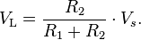
The potentiometer can be used as a voltage divider to obtain a manually adjustable output voltage at the slider (wiper) from a fixed input voltage applied across the two ends of the potentiometer. This is the most common use of them.
The voltage across R_\mathrm{L} can be calculated by:

V_\mathrm{L} = { R_2 R_\mathrm{L} \over R_1 R_\mathrm{L} + R_2 R_\mathrm{L} + R_1 R_2}\cdot V_s.
If R_\mathrm{L} is large compared to the other resistances (like the input to an operational amplifier), the output voltage can be approximated by the simpler equation:

V_\mathrm{L} = { R_2 \over R_1 + R_2 }\cdot V_s.
(dividing throughout by R_\mathrm{L} and cancelling terms with R_\mathrm{L} as denominator)
As an example, assume

V_\mathrm{S} = 10\ \mathrm{V}R_1 = 1\ \mathrm{k \Omega}R_2 = 2\ \mathrm{k \Omega}, and R_\mathrm{L} = 100\ \mathrm{k \Omega}.
Since the load resistance is large compared to the other resistances, the output voltage V_\mathrm{L} will be approximately:

{2\ \mathrm{k \Omega} \over 1\ \mathrm{k \Omega} + 2\ \mathrm{k \Omega} } \cdot 10\ \mathrm{V} = {2 \over 3} \cdot 10\ \mathrm{V} \approx 6.667\ \mathrm{V}.
Due to the load resistance, however, it will actually be slightly lower: ≈ 6.623 V.
One of the advantages of the potential divider compared to a variable resistor in series with the source is that, while variable resistors have a maximum resistance where some current will always flow, dividers are able to vary the output voltage from maximum (V_S) to ground (zero volts) as the wiper moves from one end of the potentiometer to the other. There is, however, always a small amount of contact resistance.
In addition, the load resistance is often not known and therefore simply placing a variable resistor in series with the load could have a negligible effect or an excessive effect, depending on the load.