http://en.wikipedia.org/wiki/Bessel_filter
Bessel filter
In electronics and signal processing, a Bessel filter is a type of linear filter with a maximally flat group delay (maximally linear phase response). Bessel filters are often used in audio crossover systems. Analog Bessel filters are characterized by almost constant group delay across the entire passband, thus preserving the wave shape of filtered signals in the passband.
The filter's name is a reference to Friedrich Bessel, a German mathematician (1784–1846), who developed the mathematical theory on which the filter is based. The filters are also called Bessel–Thomson filters in recognition of W. E. Thomson, who worked out how to apply Bessel functions to filter design.[1]
Contents[hide] |
[edit]The transfer function


where  is a reverse Bessel polynomial from which the filter gets its name and
  is a frequency chosen to give the desired cut-off frequency. The filter has a low-frequency group delay of
  .
.
is a reverse Bessel polynomial from which the filter gets its name and is a frequency chosen to give the desired cut-off frequency. The filter has a low-frequency group delay of .[edit]Bessel polynomials

The transfer function of the Bessel filter is a rational function whose denominator is a reverse Bessel polynomial, such as the following:


The reverse Bessel polynomials are given by:[2]

where

[edit]Example


The transfer function for a third-order (three-pole) Bessel low-pass filter, normalized to have unit group delay, is

The roots of the denominator polynomial, the filter's poles, include a real pole ats = −2.3222, and a complex-conjugate pair of poles at s = −1.8389 ± j1.7544, plotted above. The numerator 15 is chosen to give a gain of 1 at DC (at s = 0).
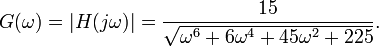
The gain is then
The phase is

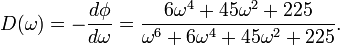
The group delay is
The Taylor series expansion of the group delay is

Note that the two terms in ω2 and ω4 are zero, resulting in a very flat group delay at ω = 0. This is the greatest number of terms that can be set to zero, since there are a total of four coefficients in the third order Bessel polynomial, requiring four equations in order to be defined. One equation specifies that the gain be unity at ω = 0 and a second specifies that the gain be zero at ω = ∞, leaving two equations to specify two terms in the series expansion to be zero. This is a general property of the group delay for a Bessel filter of order n: the first n − 1 terms in the series expansion of the group delay will be zero, thus maximizing the flatness of the group delay at ω = 0.
No comments:
Post a Comment